
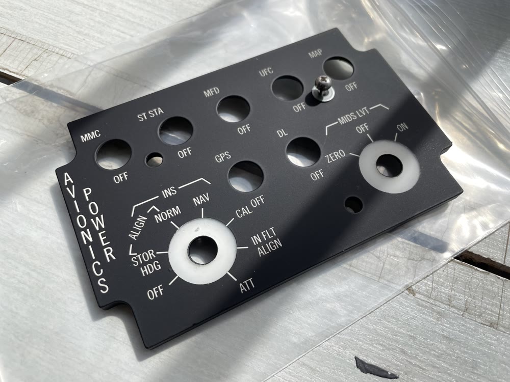
The type, colour and surface character seen with the lighting off; the clarity, uniformity and edge control seen when it is on; and the way several panels work together all contribute to real-world performance. Understanding how these factors influence one another is the starting point for an integrally illuminated panel.
Different applications call for different design approaches
Desktop simulation equipment, classroom trainers and high-fidelity cockpit projects place different demands on appearance, illumination, mounting and maintenance. UV printing, surface screen printing, masking coatings and machined legends can each suit a valid application; the right choice depends on how a project weighs visual identification, function, structural integration and repeatability.
Union Avionics focuses on applications where fidelity and system integration matter. Material, mechanical structure, surface coatings, legend forms, internal light distribution, light sources and assembly are therefore considered together from the beginning. Legends need sufficient contrast with the backlight off and clear edges when illuminated, while stray light around mounting holes, edges and non-legend areas must also be controlled.
Recognition, compatibility and ease of use
Appearance, function and straightforward integration are balanced around the needs of the particular project.
Structure, legends and lighting developed together
The manufacturing process is built around readability, uniformity, mounting relationships and repeatability.
Integrated illumination begins with the whole panel
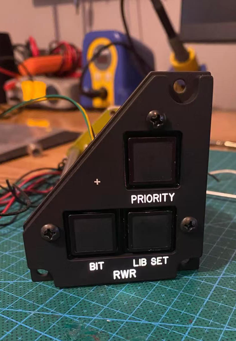
An aviation-style integrally illuminated panel brings information markings, panel structure and internal lighting into one design. The illuminated legend outline, brightness distribution and mounting relationships are considered alongside the daytime appearance and layout.
These elements affect one another. Legend machining defines the transmitted-light boundary; coatings influence colour and brightness; the internal structure changes the light path; and mounting can affect edge control. The aim is a coordinated result across daytime appearance, night illumination and installed use.
Uniform illumination
comes from repeated light-path validation
Uniformity is influenced by light-source position, legend layout, internal structure, light paths and edge treatment. Different combinations can create hot spots near legends, local dark areas or light leaking from the edges.
We first establish the intended optical path and structure, then make a validation sample to observe under illumination. Experience guides the next adjustments, with the aim of giving legends, lines and markings of different sizes an appropriate and coordinated brightness on the same panel.
Local excess brightness changes a legend's shape
Bright areas can make fine strokes appear thicker and reduce the separation between adjacent legends.
Different positions need individual attention
Legend size, location and the available internal space all need to be considered within the complete light path.
Non-legend areas also need control
Controlling stray light around mounting holes, panel edges and other opaque areas preserves the night-time visual boundary and overall appearance.
Substrate, optical base coat and top coat
all shape the result
We use a high-transmission, low-haze acrylic substrate selected for optical performance and machining stability. Stable material thickness helps control legend depth, light transmission and consistency between parts.
Core characteristics such as transmission, haze, mechanical strength and thermal behaviour sit within the reference range of the relevant aviation-panel material guidance. Before a batch enters production, its usable area is also checked for thickness and visible condition.
Stable thickness keeps machining controllable
Thickness directly influences legend depth, transmitted-light performance and assembly relationships.
A clean, even foundation for illuminated legends
The optical white layer participates in light distribution and affects illuminated colour, brightness and edge quality.
Colour and surface sheen work together
An appropriate matt finish reduces reflections while supporting daytime readability, handling durability and visual consistency across the cockpit.
Legends and markings follow defined design references
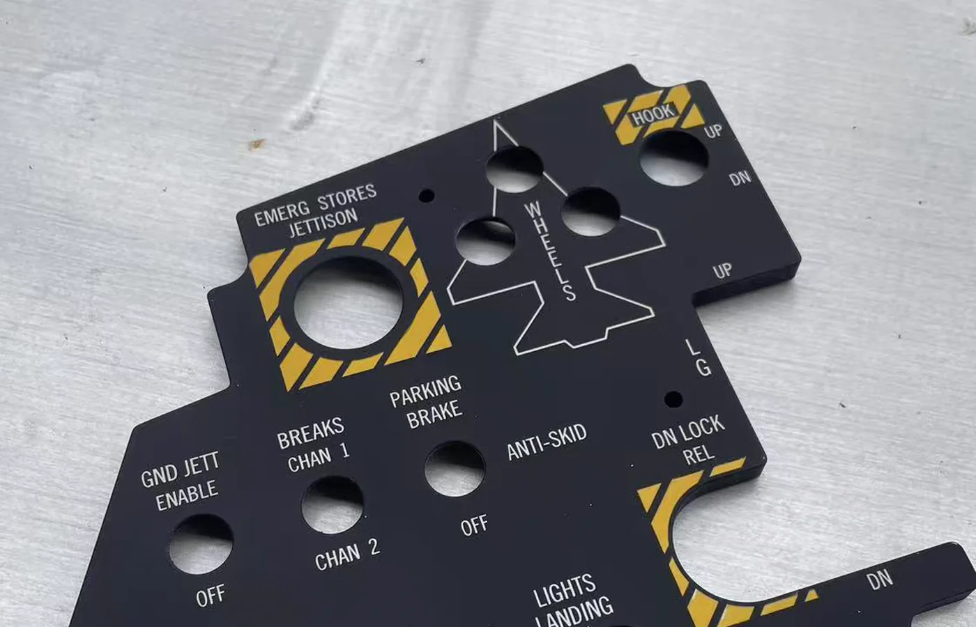
Cockpit-panel legends use defined relationships for height, width, stroke, spacing and layout. We draw them individually from the relevant panel information and applicable military aviation panel design guidance, balancing those dimensional relationships with readability at a normal viewing distance.
Multicolour markings likewise follow applicable guidance for line width, spacing and colour boundaries. Accurate proportions and positions keep information levels clear and allow the panel to read as one coherent design.
A panel also belongs
to a complete mounting system
Different mounting positions use different fasteners. We control the outline, mounting holes and key dimensions from applicable aviation-panel design guidance. DZUS quarter-turn fasteners serve panels or equipment that need quick removal, while dedicated captive panel screws connect an integrally illuminated panel to its mounting plate.
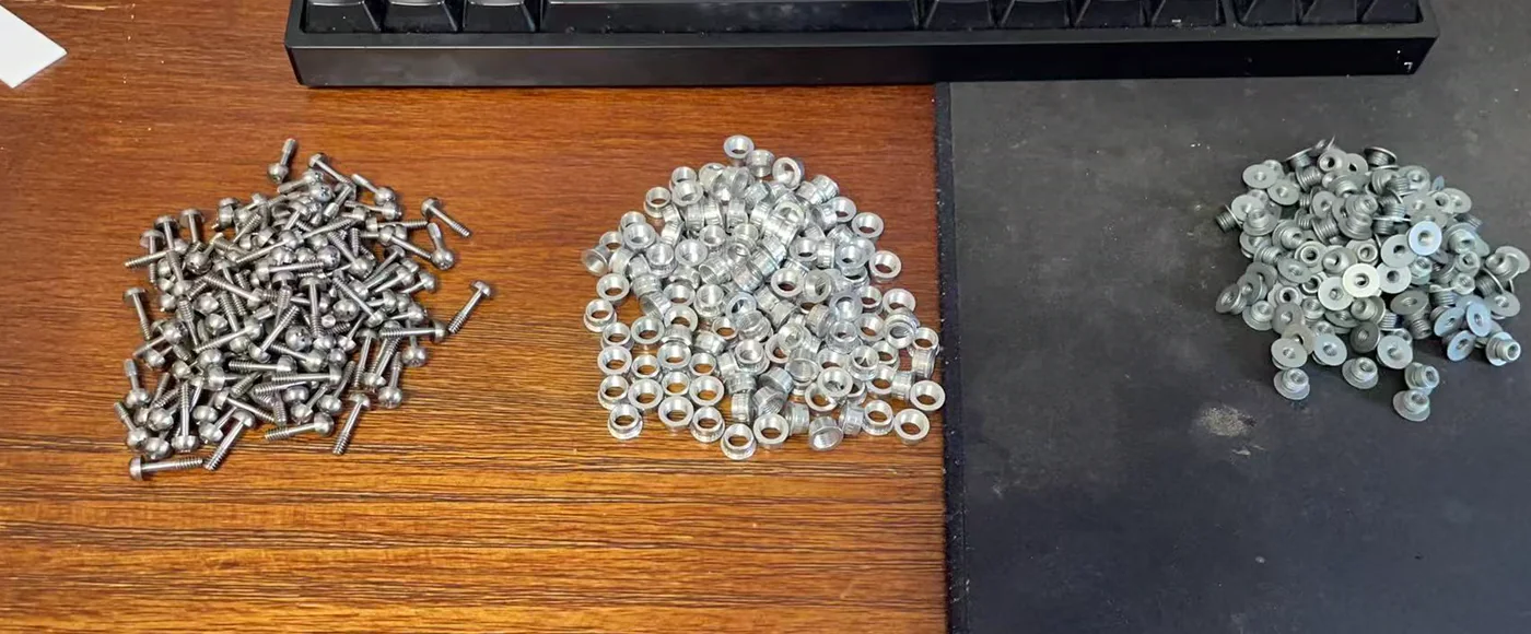
DZUS quarter-turn fastening
Used where a panel or equipment assembly needs quick removal, making system integration and maintenance more straightforward.
Type IV and Type V incandescent panels, and Type VII LED panels
The panel type is selected around the project structure, lighting method, intended visual result and maintenance requirements, with legend brightness, illumination uniformity and performance in the installed environment considered during design and validation.
Dedicated captive panel screws
These fasteners connect the illuminated panel to its mounting plate and remain with the panel when loosened. They simplify removal and prevent loose hardware from being lost. The detail is rarely central in a front view, but it directly affects assembly, maintenance and the completeness of the equipment.
Readable by day,
controlled at night
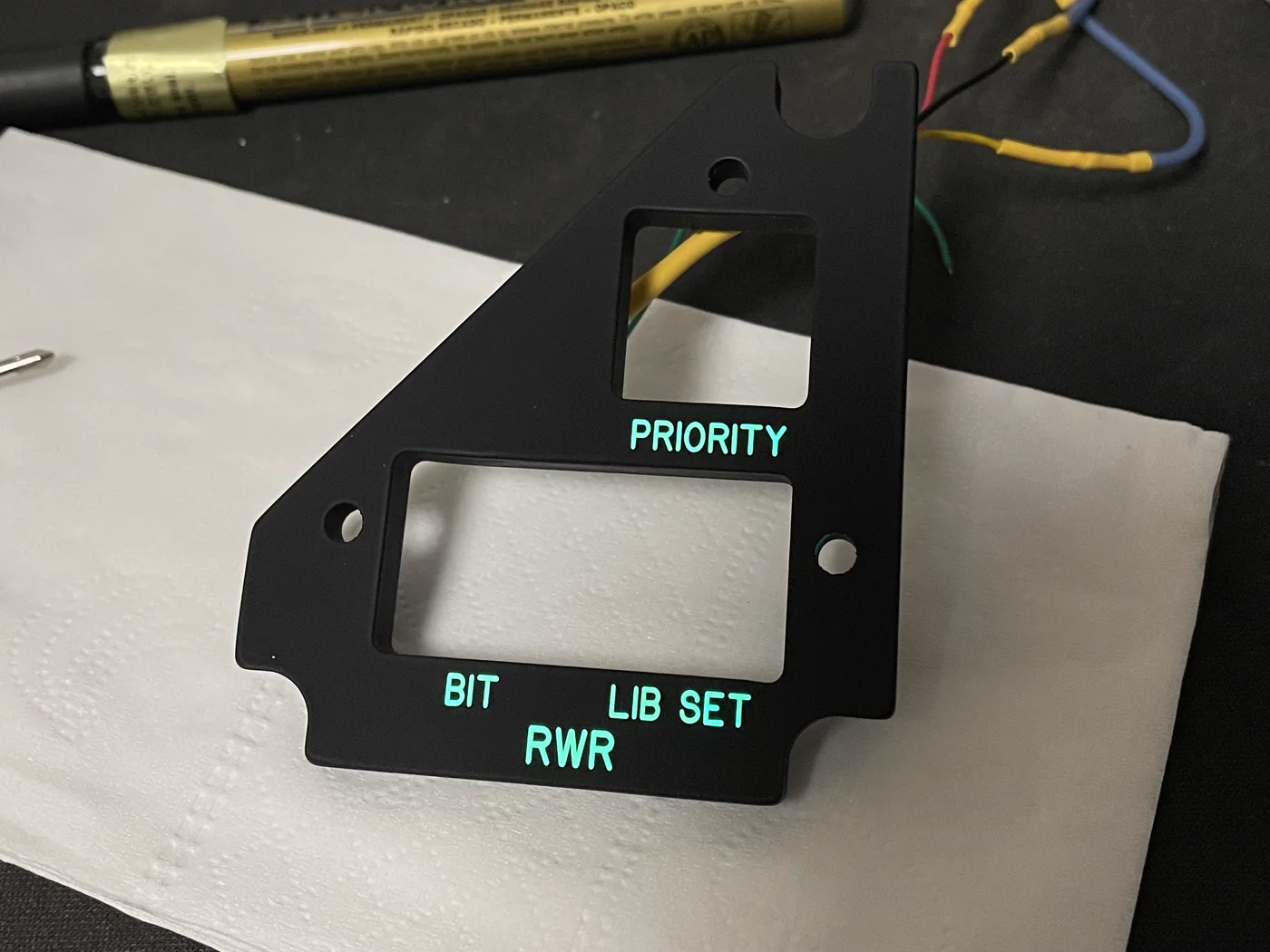
Backlighting is designed for readability and coordination with its environment. Legend brightness has a defined operating purpose and needs to sit naturally beside neighbouring panels. Excess brightness can create glare in a dark cockpit, soften legend edges and obscure fine detail.
Legends remain clear with the lighting off
Defined outlines, line work and surface contrast provide a readable foundation before illumination is applied.
Clear when lit without overwhelming a dark cockpit
Excess brightness spreads strokes, hides detail and adds unnecessary visual load in a dark environment.
Light only where light is intended
Stray light from holes, edges and other opaque areas quickly undermines the visual quality of a panel.
Several panels remain coordinated together
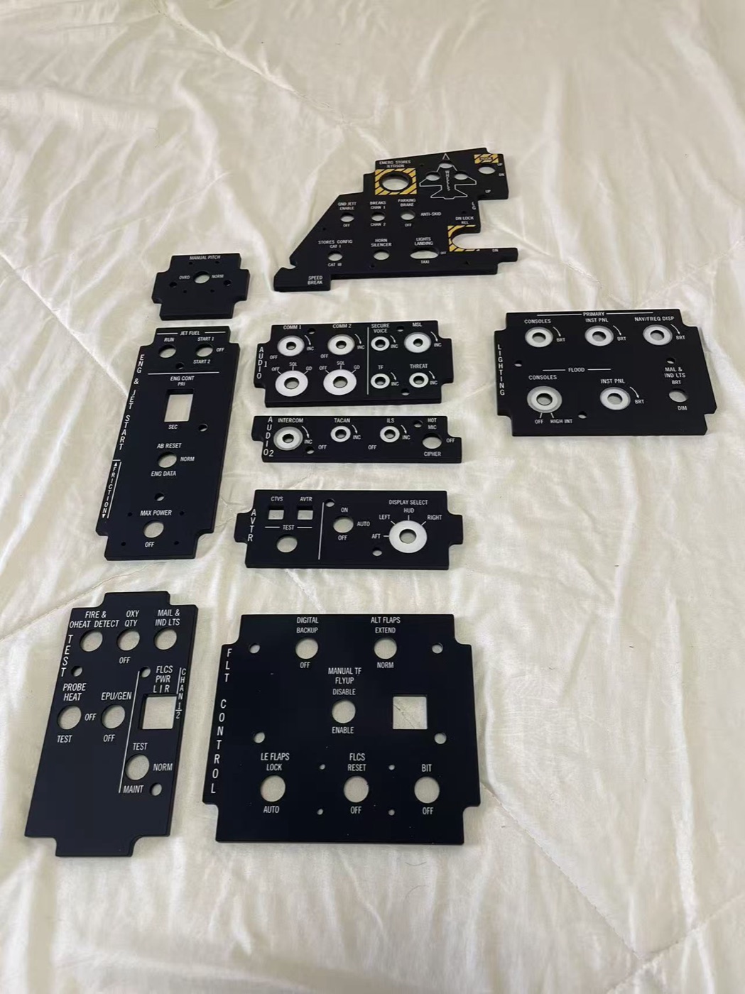
Colour, legends, brightness and surface finish need to remain consistent across panels and production batches.
Repeatable performance
comes from repeated sample validation
Drawings define dimensions and appearance, but illumination still needs to be observed in a physical sample. Materials, coatings, legends and lighting influence one another, and a sample is only the start of validation. Repeatable results also depend on judgement developed through repeated manufacture: knowing what to observe, how to locate a deviation and how to turn one good result into a stable process.
- Set the target
Define dimensions, legends, mounting relationships and expected performance by day and by night.
- Build a sample
Observe the actual result produced by the selected material, coating, legend and lighting combination.
- Adjust the result
Check brightness, uniformity, legend edges and stray light, then correct the design progressively.
- Stabilise manufacture
Apply the validated method to production so panels and batches remain coordinated.
Green illumination
does not mean NVIS compatibility
Greens that look similar to the eye do not necessarily have the same spectrum or behaviour with night-vision equipment. NVIS compatibility requires instrumented measurement and validation of spectral, chromaticity and luminance characteristics. It cannot be established from a similar colour, a green filter or a camera image.
NVIS-style describes colour and visual direction only. Until the relevant testing is complete, we do not describe a product as NVIS compatible or NVIS certified.
Fidelity comes from details that agree with one another
Type proportions, colour and surface character shape the front view; brightness, uniformity and installed coordination carry that fidelity into use.
From legends and light to mounting relationships, every detail serves one coherent and natural operating experience.