Flight simulation avionics · For ground simulation onlyContact
SECOND PROTOTYPE DESIGN
IN DEVELOPMENT
AN/ALE-47 · F-16 BLOCK 50CMDS Panel
An AN/ALE-47 CMDS control panel developed for F-16 Block 50 ground-based simulator cockpits. The project combines a complete equipment form, military-aircraft panel dimensions and DZUS mounting with dot-matrix VFDs, Type VII illumination, and UA-developed electronics and software.
Adjusting the prototype and preparing for revalidation
Project initiation
First prototype validation
Adjust prototype and revalidate
Pre-order
Production
Delivery
DESIGN OBJECTIVES
A complete CMDS panel, not an appearance-only replica
The CMDS is designed as a complete simulator device: its dimensional system, DZUS mounting, VFD display, illuminated panel, controls, enclosure, electronics and software must work together.
Dimensions and mounting
A complete equipment form designed around DZUS mounting
The face panel follows a military-aircraft panel dimensional system, while the controls, displays, rear enclosure and interface are designed as one complete unit. Four original DZUS fasteners are pre-installed by default, with corresponding military-pattern fasteners used in the panel assembly.
VFD display
Balancing the dot-matrix format, full function and component availability
The standard design uses two commercial-grade 8-digit, 5×7 dot-matrix VFDs from the same display family as the original-specification devices. This retains the complete display content and function while improving availability and controlling the complete-unit cost. A four-module 4-digit VFD arrangement can be discussed as a custom configuration subject to requirements and component availability.
Panel and illumination
Optical-grade acrylic with Type VII LED illumination
The panel uses optical-grade acrylic. Illuminated legends are laser processed, non-illuminated markings are screen printed, and character size and line width follow military-aircraft panel design practice. The default Type VII panel uses SMD LEDs in standard warm light or NVIS-style green; a warm-light T1 aviation incandescent version can also be commissioned, but NVIS filter caps are not currently offered.
Controls and status
Every control and status display participates in simulator operation
Toggle switches, Grayhill rotary selectors, VFDs and LED status windows are functionally reproduced and follow CMDS states in DCS World or Falcon BMS. The standard configuration uses selected toggle switches; all toggle positions may be replaced with original components after availability is confirmed.
Structure and system
7075 aviation aluminium enclosure with UA-developed hardware and software
The rear enclosure uses 7075 aviation aluminium with a multi-layer industrial coating referenced against the physical FS 37038 Aviation Black chip in the SAE Federal Standard colour deck. The controller, VFD drive, switch input, illumination control, PCB and PCBA are designed and completed by UA, with the computer connection provided through a USB-to-4PIN aviation connector cable.
SOFTWARE CONNECTION
Union Avionics Simulator Center
Union Avionics Simulator Center connects the CMDS to DCS World and Falcon BMS. Toggle switches, rotary selectors, the VFD inventory display and LED status windows follow the corresponding simulator states rather than serving as static visual details.
DCS WORLDSupported through Simulator Center.
FALCON BMSSupported through Simulator Center.
USB DATAData and device connection through a USB-to-4PIN aviation connector cable.
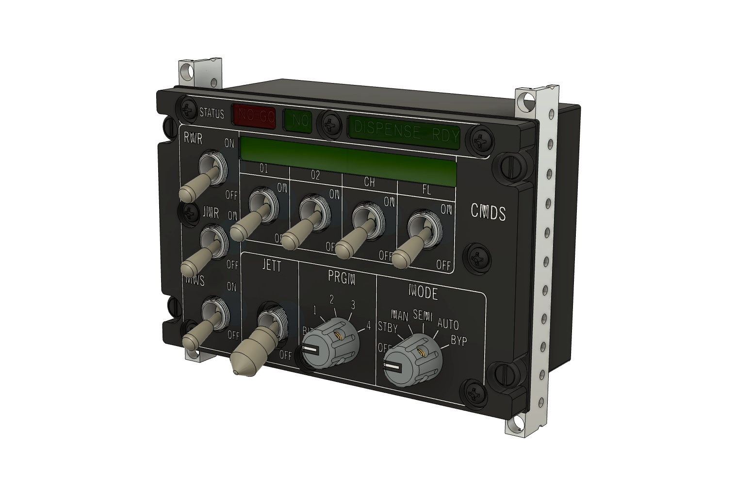
Second prototype design frozen
Based on the first-prototype results, the panel structure, VFD display area, complete control set, rear enclosure and DZUS mounting relationship were reconfirmed for the second-prototype assembly design.
+Second CMDS prototype assembly design · frozen on 23 June 2025
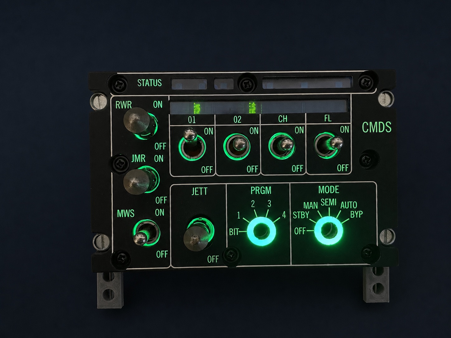
First prototype illumination, VFD and screen-printing tests
The first physical prototype was used to test the Type VII illumination, VFD display module and screen-printed markings together. These tests confirmed the main operating path and also exposed errors that could only be judged on the assembled hardware.
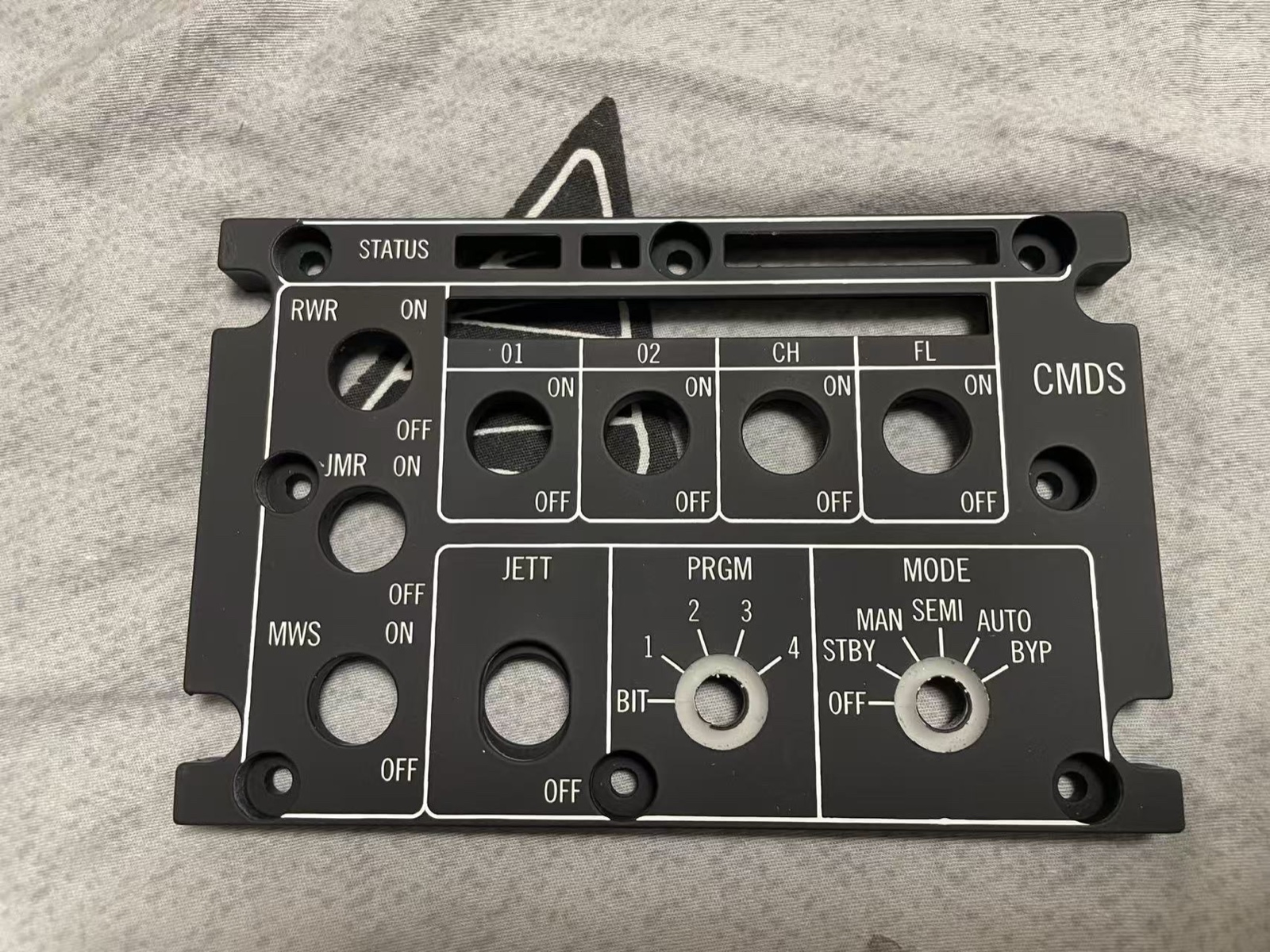
Prototype panels do not enter the precision coating process specified for finished products, because they remain subject to repeated assembly and adjustment. Visible coating, edge and assembly imperfections in these photographs represent the prototype state and will not remain on production units.
The second-prototype design corrects the illumination and screen-printed linework and enlarges the VFD window opening. These changes will be checked again on the next physical build rather than treated as complete from the drawing alone.
+First-prototype illumination test · background prepared for public presentation+First-prototype screen-printing test · known errors retained in the record
VFD display-module prototype test
CURRENT DEVELOPMENT STATE
The page shows the second prototype design before its next physical build. Final details may continue to change after machining, assembly and revalidation. The product is intended only for ground-based simulation and is not airworthy equipment.
Follow the next CMDS prototype
Join the UA Discord to follow physical production and revalidation, or discuss a simulator-cockpit project.