Flight simulation avionics · For ground simulation onlyContact
CURRENT PROTOTYPE VIEW
IN DEVELOPMENT
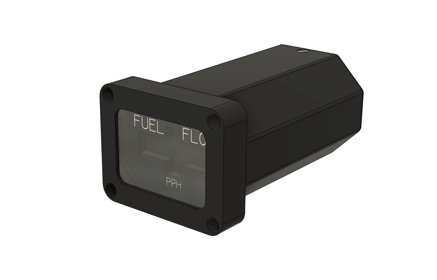
FUEL FLOW INDICATOR · F-16 SERIESFFI
A fuel-flow instrument developed for F-16 ground-based simulator cockpits. Its OLED digital dial keeps instantaneous fuel flow within the cockpit sightline, while the physical dimensions, digit forms and transitions, bright-environment readability and simulator connectivity are designed as one system.
Building the dimensions, display and viewing experience together
The FFI is not a generic display placed inside an enclosure. Its face proportions, mounting pattern, digital dial, optical window, housing and software drive must work together in one complete instrument. The items below identify what has been completed and what still requires whole-prototype validation.
Dimensional basis
Starting with a physical reference instrument
UA used a military-grade ground-simulator FFI as the measurement reference for the face proportions, mounting pattern and instrument envelope. The four M4 mounting positions have now been machined and physically trial-fitted.
Display design
Redesigning the OLED digital dial
The FFI retains a purely digital reading format, while its digit forms and transition behaviour are tuned item by item for rapid changes. The internal display assembly already runs from simulator-platform data; clarity and timing at different viewing distances will continue through complete-prototype validation.
Optical window
Making high-transmission AR optical glass part of the display
The custom high-transmission optical glass uses an AR coating to reduce surface reflections in bright environments and preserve better viewing conditions for the OLED values. The glass has been completed; the final result will be confirmed after installation in the complete prototype.
Structure and finish
7075 aviation aluminium bezel and aluminium rear cover
The CNC-machined 7075 aviation aluminium bezel will next receive surface preparation and a multi-layer industrial coating referenced against the physical FS 37038 Aviation Black chip in the SAE Federal Standard colour deck. The aluminium rear cover has completed machining and matte anodising.
SOFTWARE CONNECTION
Union Avionics Simulator Center
Union Avionics Simulator Center is developed by UA. It receives fuel-flow data from DCS World and Falcon BMS, then lets the FFI draw and update its OLED digital dial. The internal display assembly has completed connection and display testing with both platforms. The complete instrument will next be used to check update timing, stability and long-duration operation.
DCS WORLDData connection and display testing completed on the internal assembly.
FALCON BMSData connection and display testing completed on the internal assembly.
USB DATAFlight data is delivered through USB and rendered by the FFI itself.
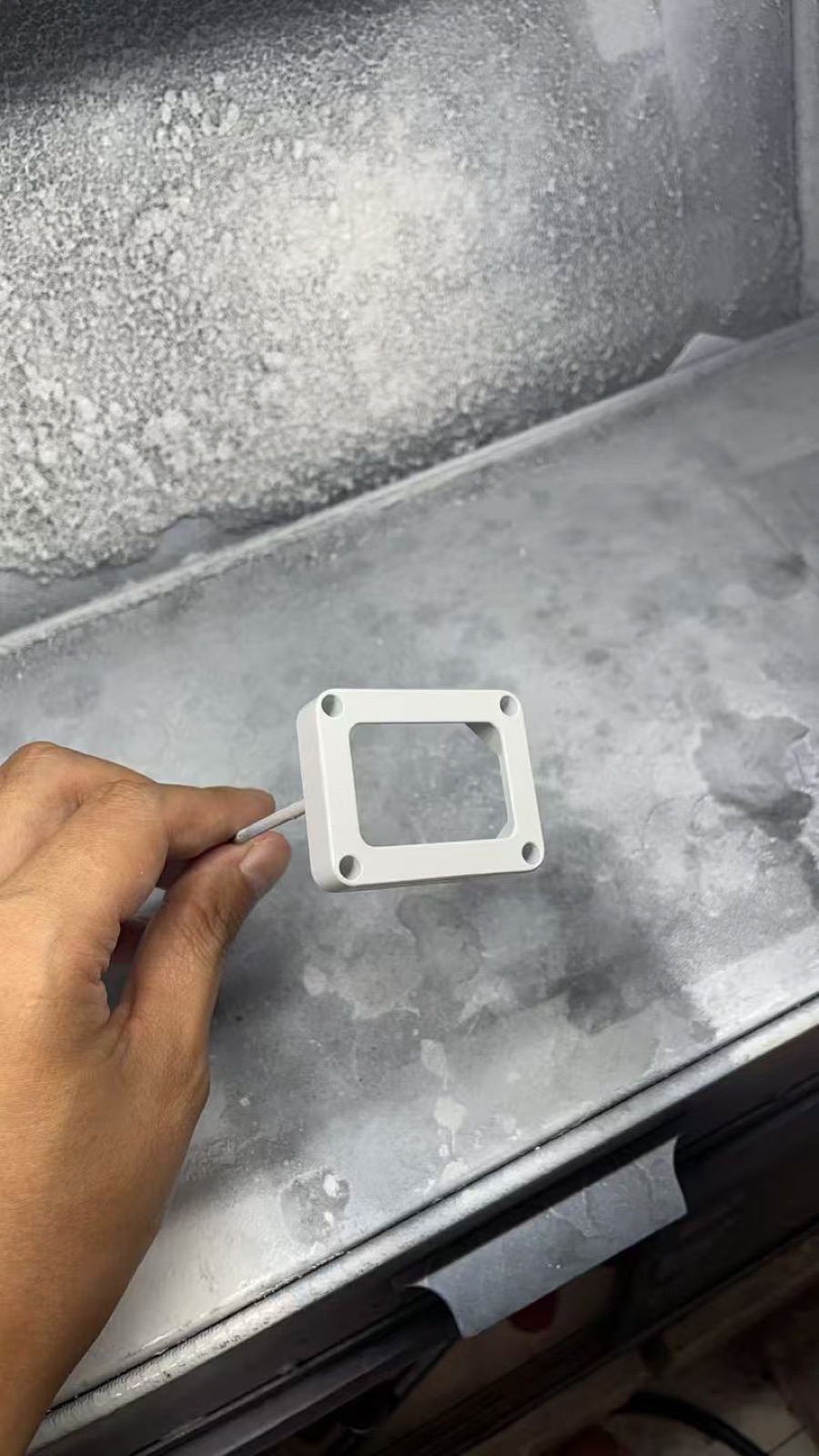
Bezel primer-coating work began
After machining and surface preparation, the aluminium bezel entered primer application. The primer establishes an even base and stable adhesion for the later multi-layer industrial coating system.
This photograph records the primer stage inside the coating booth. The light-coloured surface is not the final FS 37038 Aviation Black finish.
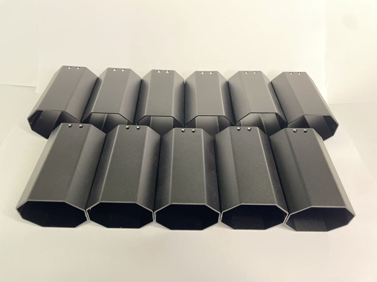
The machined aluminium rear covers completed matte-black anodising. This finish provides surface protection while keeping the rear structure visually restrained inside a simulator cockpit.
The batch will continue through trial assembly so that mounting positions, enclosure clearances and the fit with the front structure can be checked on the complete prototype.
CNC parts completed and animated digital dial demonstrated
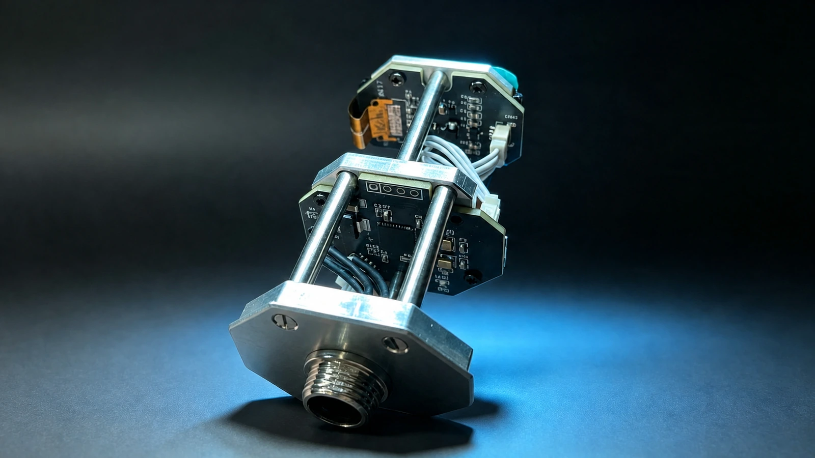
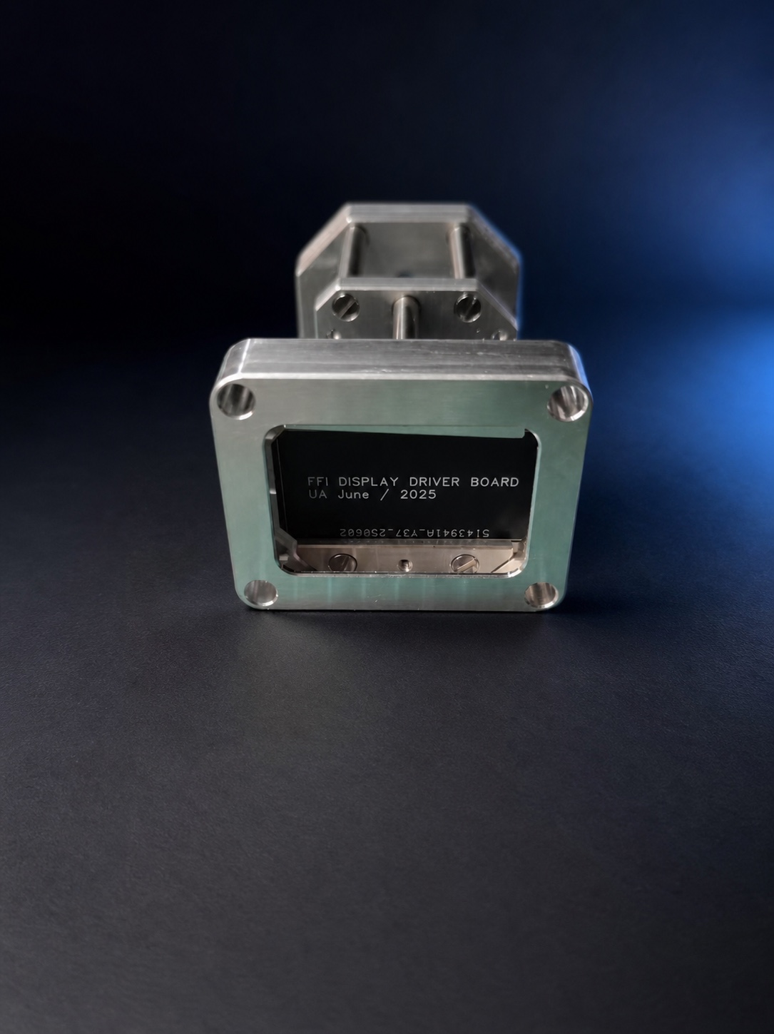
The first set of CNC-machined structural parts was assembled with the display-driver board, bringing the bezel, display position and internal mounting relationship into a physical prototype for the first time.
The same-day video records the OLED animated digital dial running on the actual display assembly. It was used to observe the digit layout and transition behaviour; the optical glass, final coating and complete viewing result were not yet part of this test.
+First CNC-machined FFI structure with the display-driver board
Animated OLED digital dial demonstrated on the actual display assembly
First prototype assembly design frozen
The first prototype assembly design was frozen with the front bezel, instrument body, display assembly, controls, mounting structure, interface and rear cover defined within one complete assembly relationship.
This version became the basis for first-article machining and assembly validation. Later revisions would follow observations from physical machining, assembly and inspection rather than adjusting the exterior only in the model.
This page shows the first complete prototype in development. Surface treatment, final assembly and the complete viewing result have not yet been confirmed and may change after testing. The product is intended only for ground-based simulation and is not airworthy equipment.
Continue the discussion on Discord
Follow later FFI development updates or discuss its integration into a ground-based simulator cockpit.