Flight simulation avionics · For ground simulation onlyContact
F-16 Radar Warning ReceiverCURRENT DESIGN VIEW
IN DEVELOPMENT

F-16 SERIESRWR

A radar-warning display project for an F-16 ground-based simulator cockpit. The design follows the 3.25-inch military-aircraft instrument envelope and combines dedicated optical filter glass with a custom high-output backlight.

IN DEVELOPMENTPage updated: August 2026
Back to all products
PRODUCT PROGRESS

Currently in engineering and prototype work

  1. Project initiation
  2. First prototype validation
  3. Adjust prototype and revalidate
  4. Pre-order
  5. Production
  6. Delivery
DESIGN OBJECTIVES

What the final product is intended to achieve

These items describe the target design. Confirmed components are identified separately; the remaining objectives continue through prototype production and verification.

Dimensional objective

3.25-inch aircraft instrument dimensional system

The front geometry, mounting holes and instrument envelope behind the bezel are designed around the corresponding dimensional system for a cockpit installation relationship closer to the original instrument.

Optical objective

Dedicated optical filter glass and high-brightness backlight

Optical filter glass with a defined spectral transmission profile is paired with a custom high-brightness backlight to compensate for display loss through the filter. This is not a claim of NVIS compatibility or certification.

Components secured

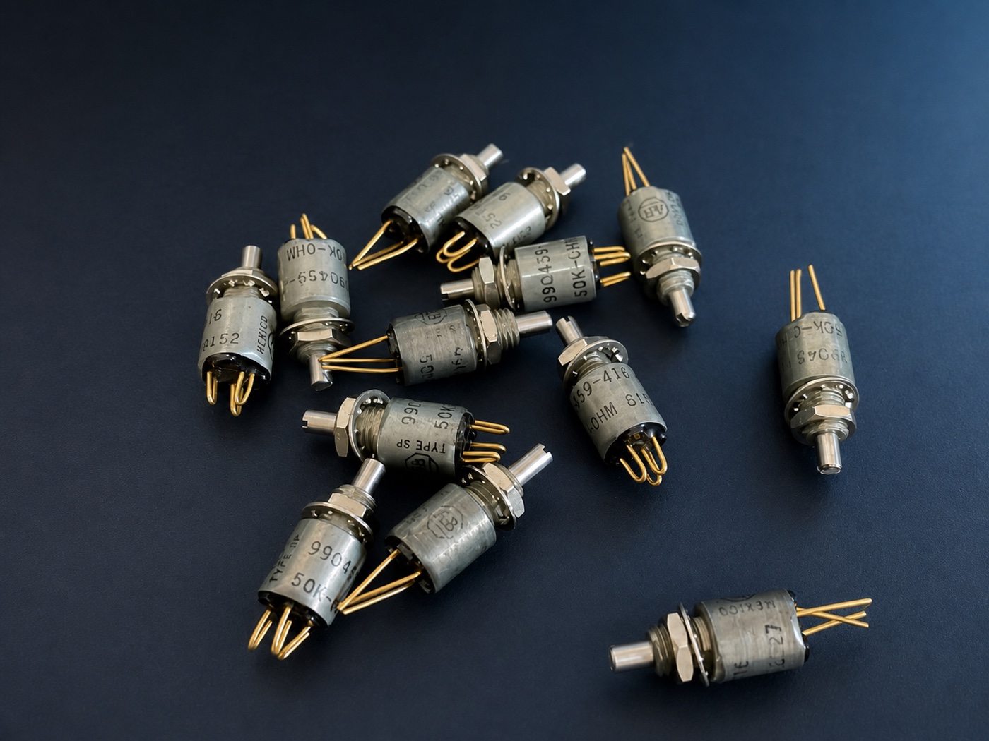
Military-grade 0.375-inch conductive-plastic potentiometer

This format is difficult to source consistently. Its firm rotational resistance avoids the loose feel common to small general-purpose potentiometers and provides deliberate, substantial feedback. UA has stocked more than 100 units to retain this format and feel in later products.

UA stock of 0.375-inch military-grade conductive-plastic potentiometers
Selected component · more than 100 units stocked
Structural objective

7075 aviation aluminium bezel and aluminium housing

The front bezel, instrument envelope and rear housing are intended to form one coherent and robust structure.

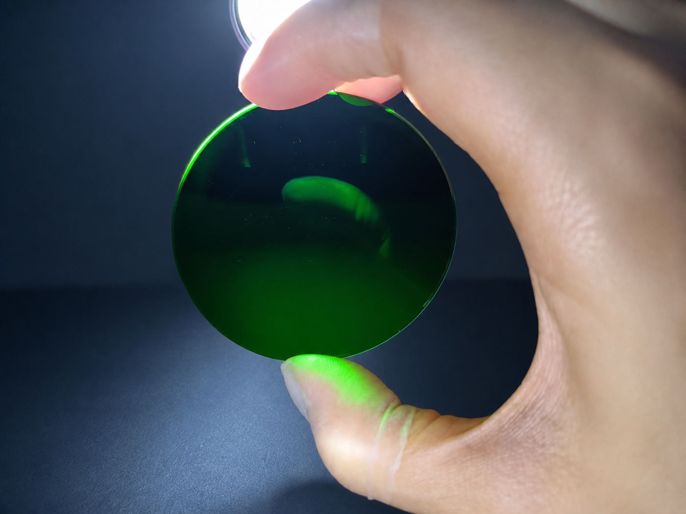
Optical coating completed and strong-light reflections compared

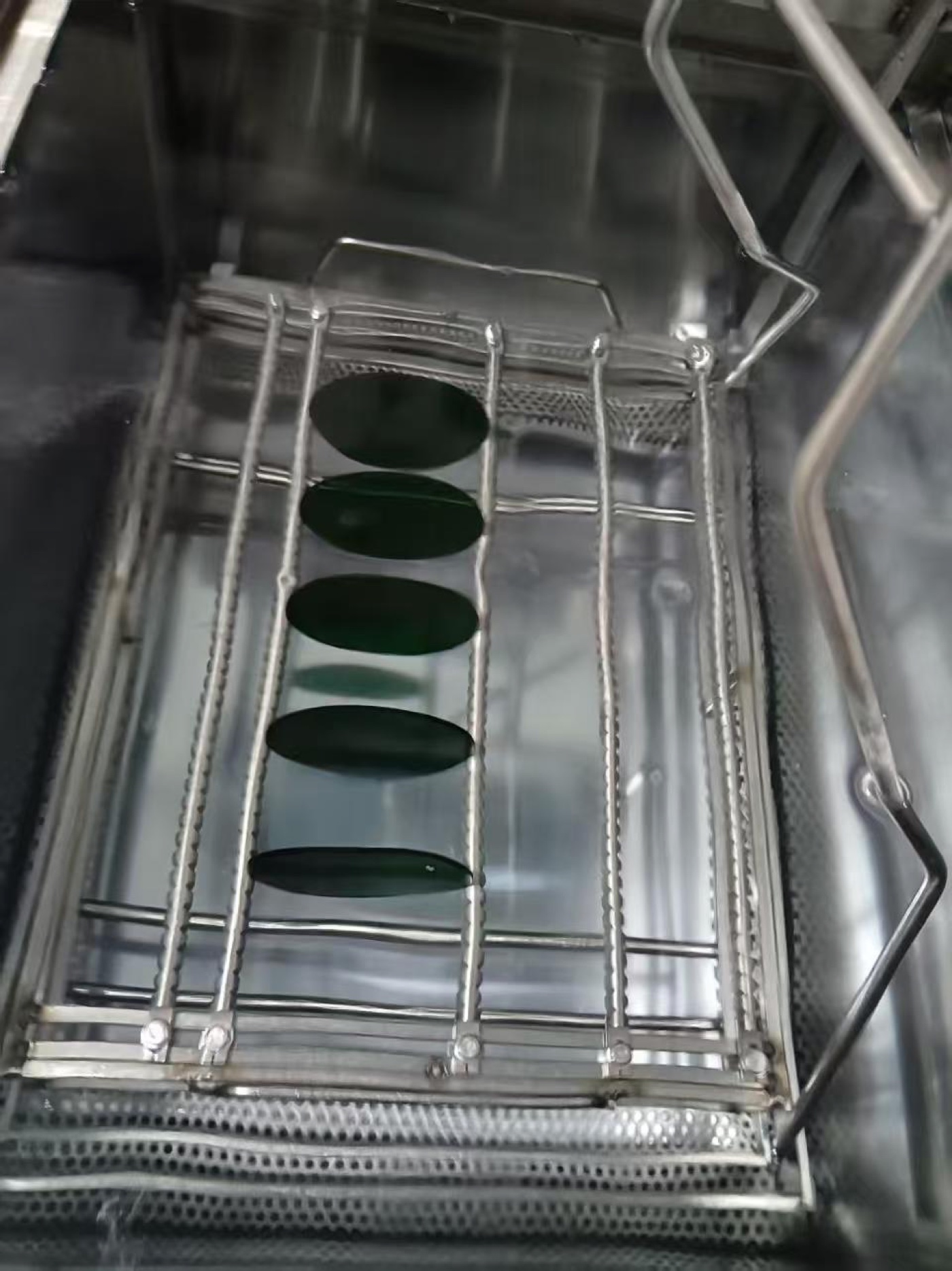
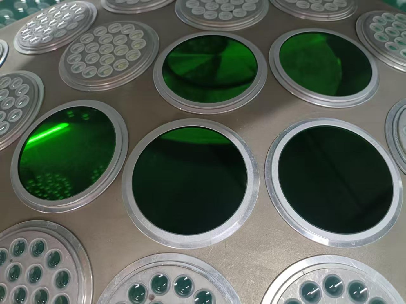
The filter-glass batch completed its optical coating process. The production photos are retained as process evidence, including the fixtures and surrounding batch parts.

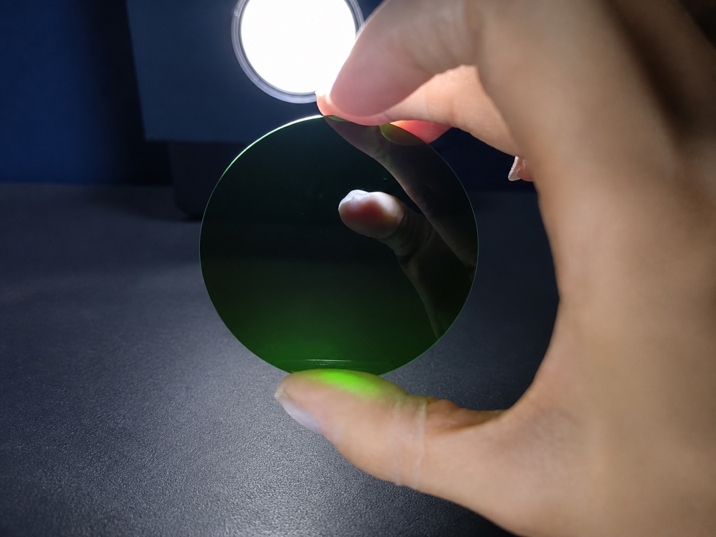
Before-and-after samples were observed under a strong inspection light to record visible changes in surface reflection, environmental reflections and overall colour. These photographs show visible differences only; they do not identify the deposition method and do not replace spectral or NVIS compliance testing.

Filter glass in the optical-coating process
Coated optical filter glass and surrounding batch parts
Before coating: surface reflection under strong illumination
After coating: surface reflection under strong illumination

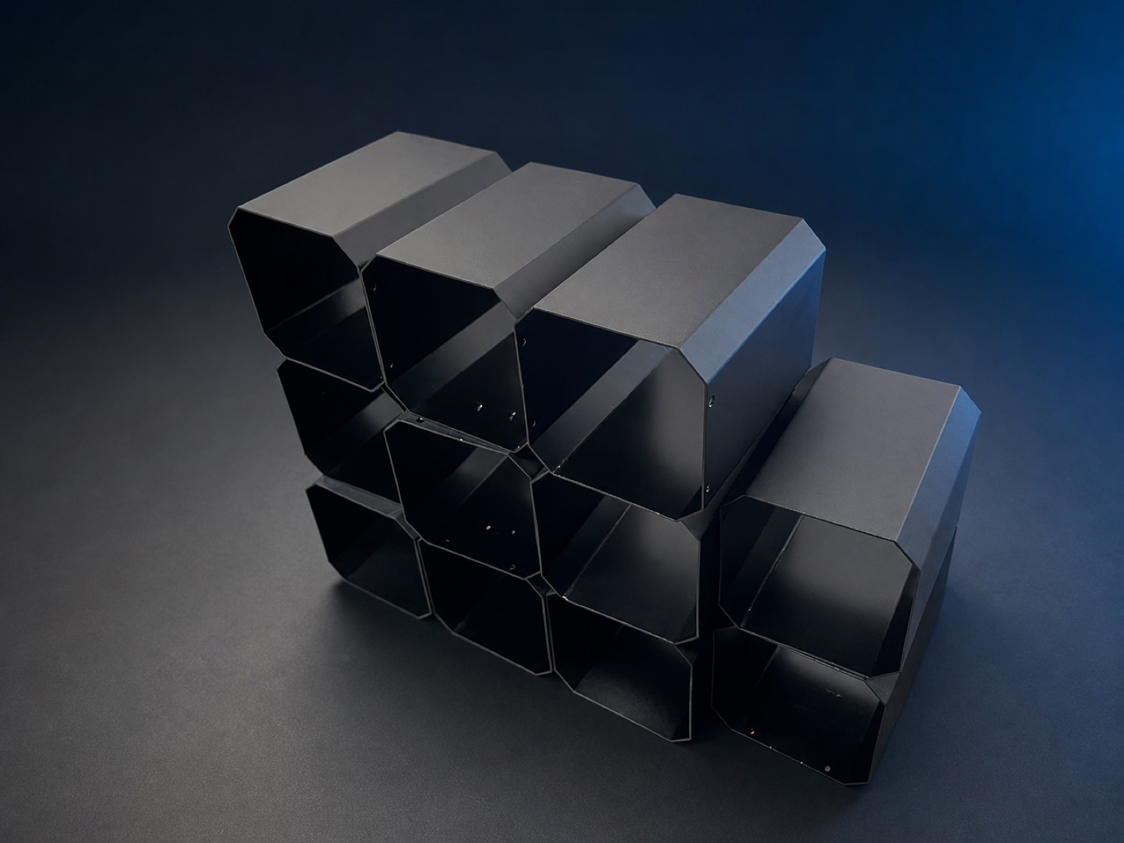
Rear covers machined and matte-black anodised

The aluminium rear cover uses a compact envelope with very limited machining allowance. Wall thickness, folds, connector openings and assembly clearances therefore leave little room for accumulated error.

Bringing these parts consistently within the design tolerances is demanding. This batch completed matte-black anodising and will continue through trial assembly and fit inspection.

Batch of matte-black anodised aluminium rear covers

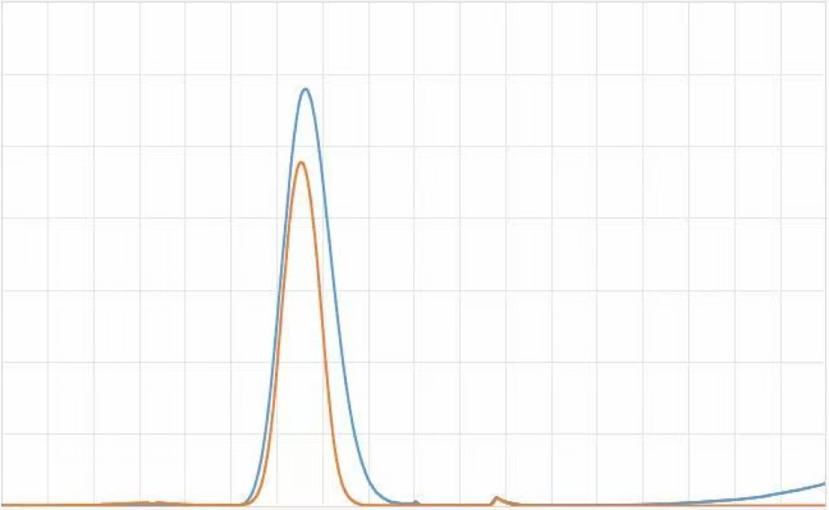
Filter glass matched against a measured reference sample

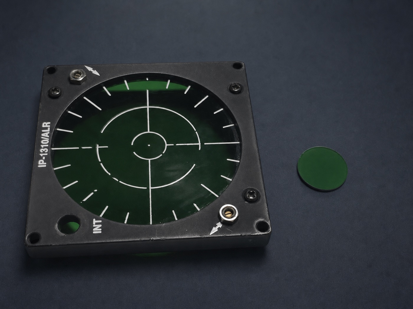
A military-grade RWR simulator bezel and its optical filter were sent to the filter-glass supplier for spectral analysis and comparison with available products.

In the comparison chart, the blue curve is the closest selected UA option. It targets a visual and spectral character close to NVIS-style filtering, but is not a claim of military NVIS compliance. Where a project requires specified NVIS performance, custom coating and corresponding testing can be evaluated at substantially higher cost.

Reference sample and selected option spectral comparison
Submitted RWR bezel and the closest selected filter sample

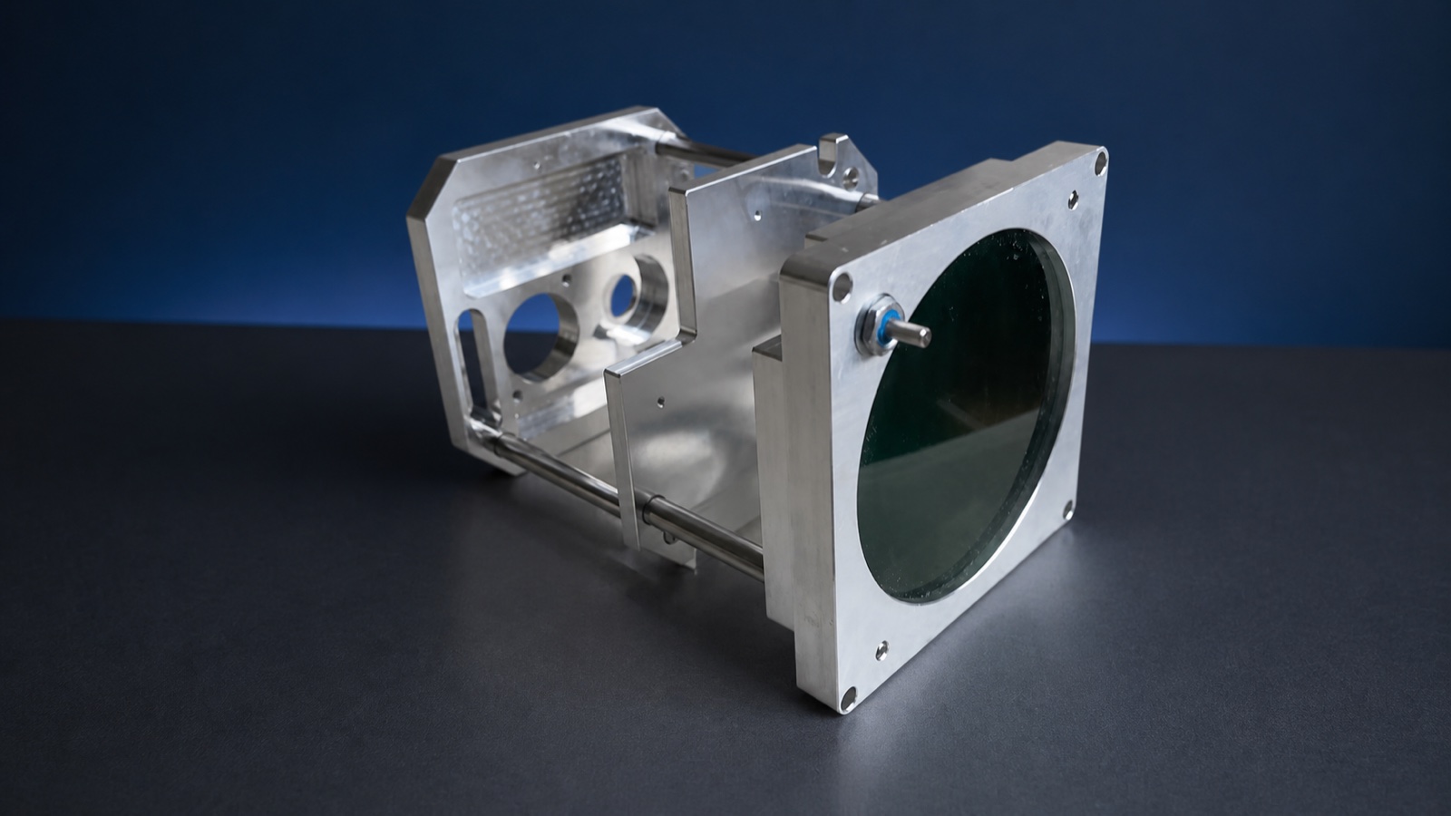
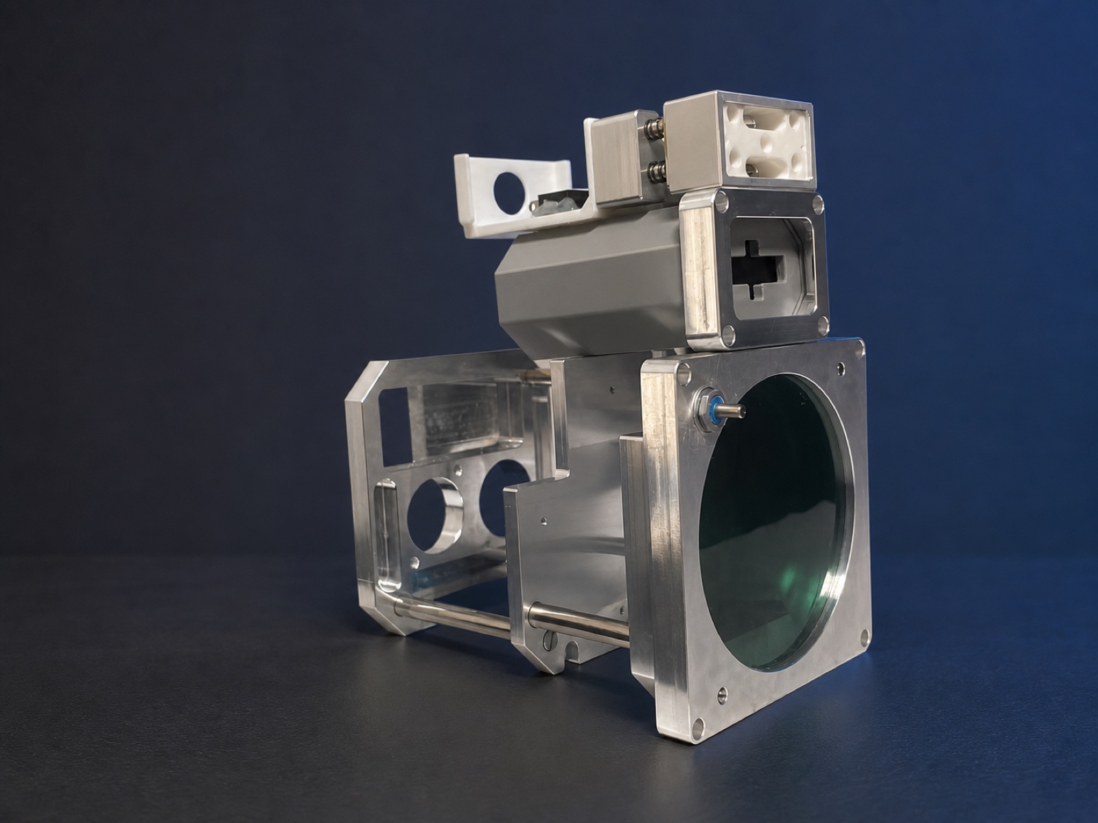
First CNC-machined prototype completed

The first complete set of RWR structural parts was CNC machined, bringing the front bezel, internal supports, display window and rear structure together as a physical assembly.

The first article was used to check manufacturability, basic assembly relationships and the available clearances between the display window, control, support rods and rear enclosure—not to represent the final surface finish.

First CNC-machined structure and front display window
Rear and internal assembly relationships of the first article

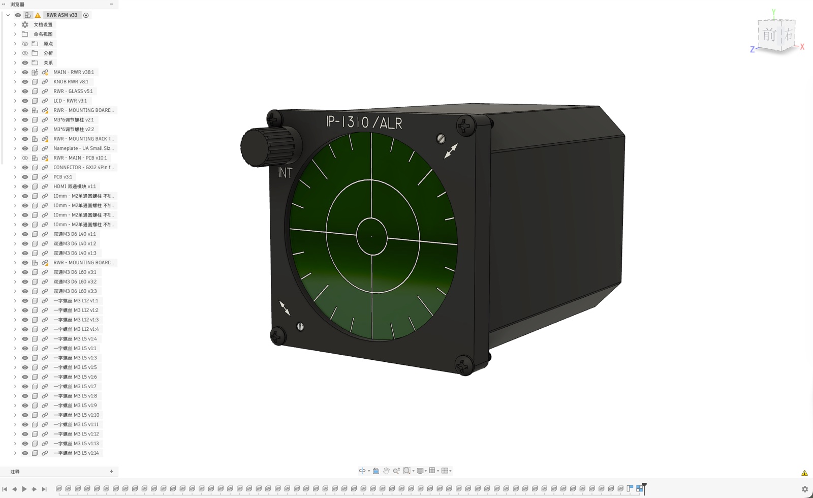
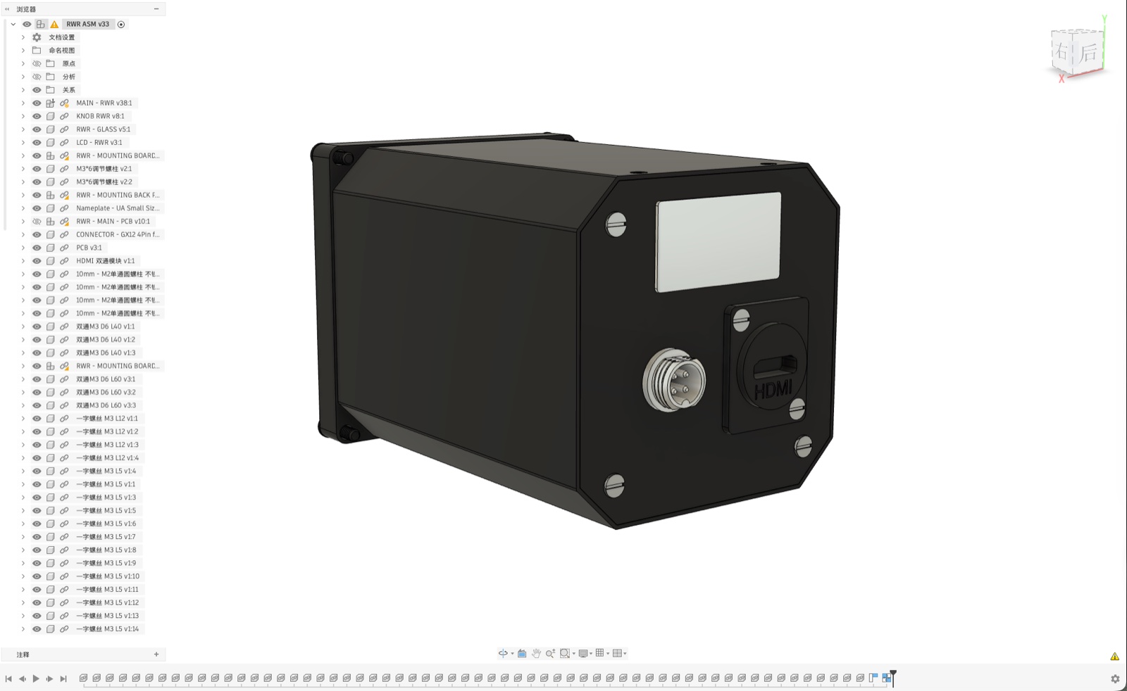
Prototype assembly design frozen for first-article machining

The first prototype assembly design was frozen, bringing the front bezel, instrument body, display components, control, mounting structure, interfaces and rear cover into one assembly relationship.

This design became the basis for first-article machining and assembly validation. Later changes are driven by the physical machining, fit and viewing results rather than appearance alone.

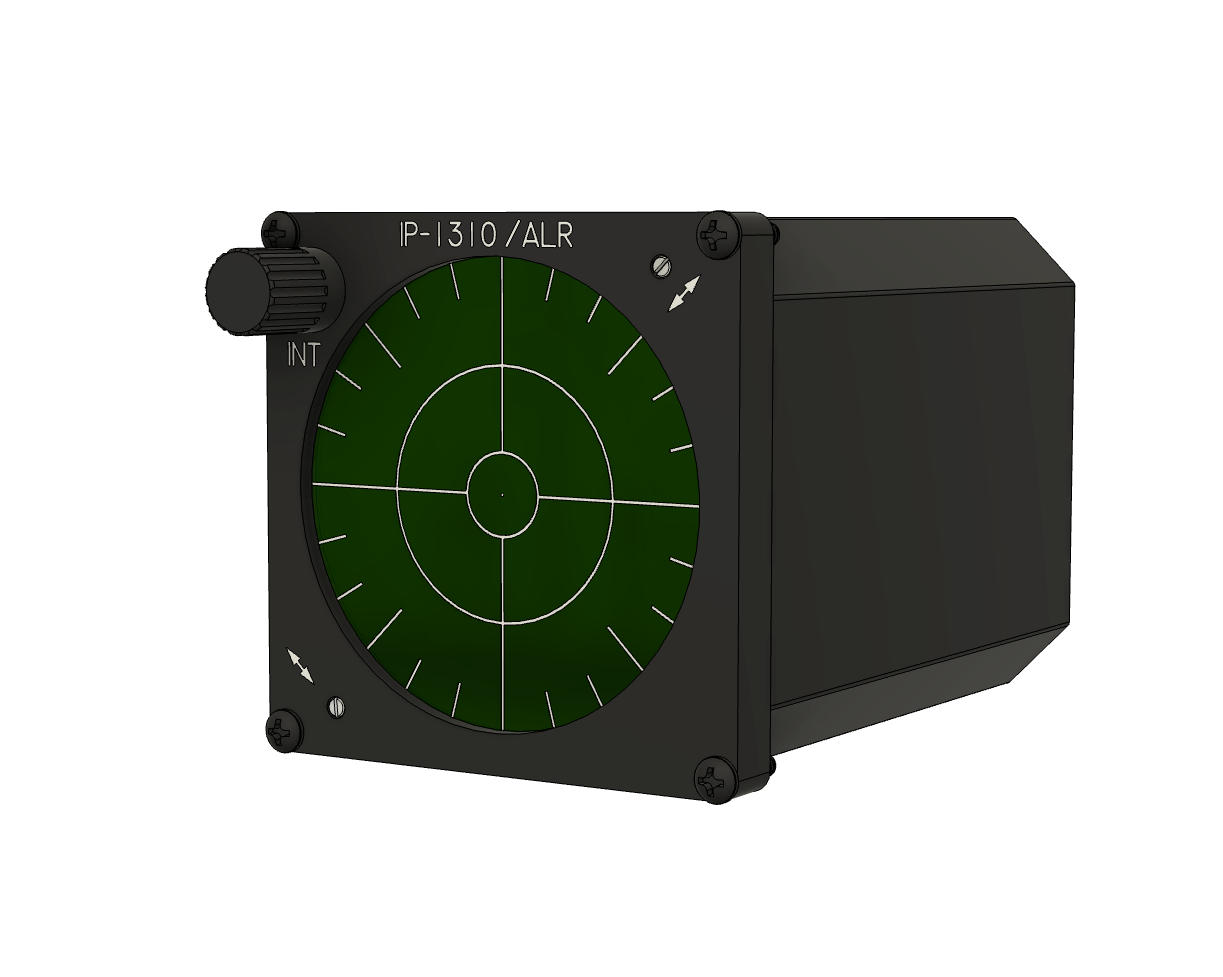
Prototype assembly design — front view
Prototype assembly design — rear view
CURRENT DEVELOPMENT STATE

The page shows a development prototype whose structure and display solution may continue to change through installation, viewing and functional testing.

Continue the discussion on Discord

Follow later development updates or discuss how the device may fit your simulator cockpit.

Open community channels
1 / 1